
Relays
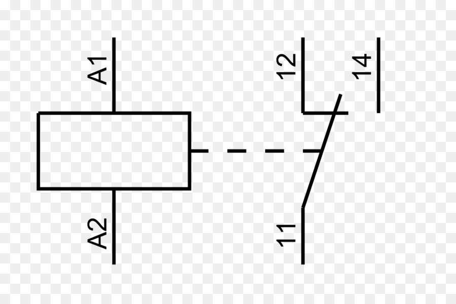
1.1 Sample Wiring Diagrams for a Normally Open Relay. Example 1: A four-pin (normally open) relay with the switch on the control circuit's positive side. Firgue1: positive side. Example 2: A four-pin (normally open) relay with the switch on the control circuit's negative side. Firgue2: negative side.

electrical schematic symbols relay Wiring Diagram and Schematics
Standard electrical IEC symbols also known as IEC 60617 (British Standard BS 3939) used to represent various devices including pilot lights, relays, timers and switches for usage in electrical schematic diagrams. Tip: Streamline your electrical design process and improve your workflow with Capital Electra X.

Electrical Schematic Symbol Relays CAD Block And Typical Drawing
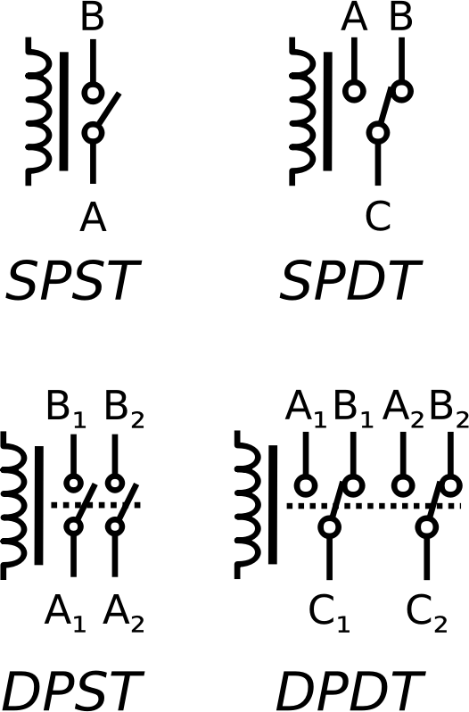
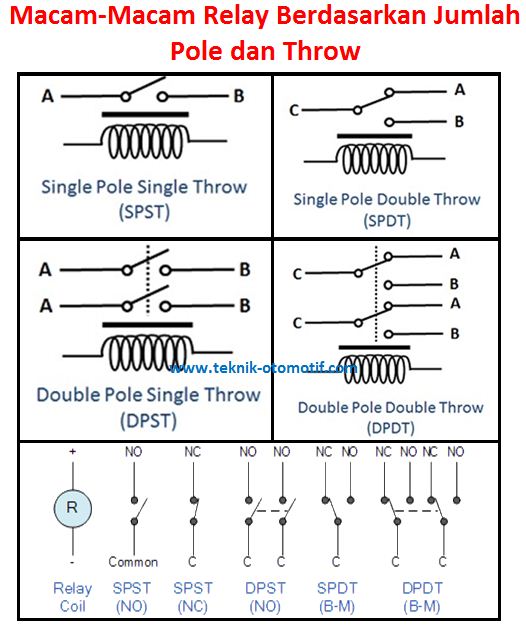
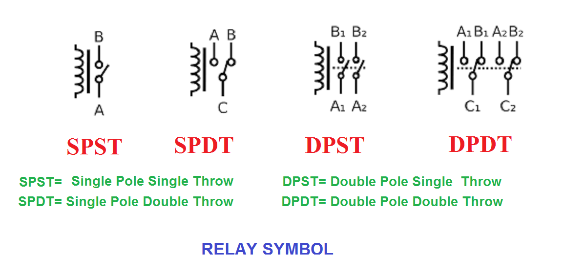
10 Types of Relay, Symbol and Working (SPST, SPDT, Solid state) A relay is a device that controls a switch position (ON or OFF) connected to a high-current circuit using a low-current signal. So it has two parts: Control and Switch part. Think of a relay like a gatekeeper or a traffic signal. When a car or pedestrian wants to cross a street.

Relay[Terminal Numbering system (relay pins) IEC schematic symbolCoil Voltage] Explained YouTube
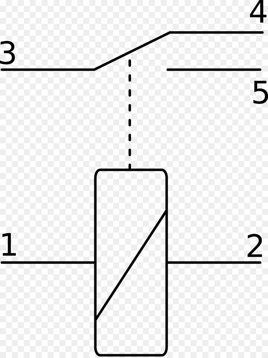
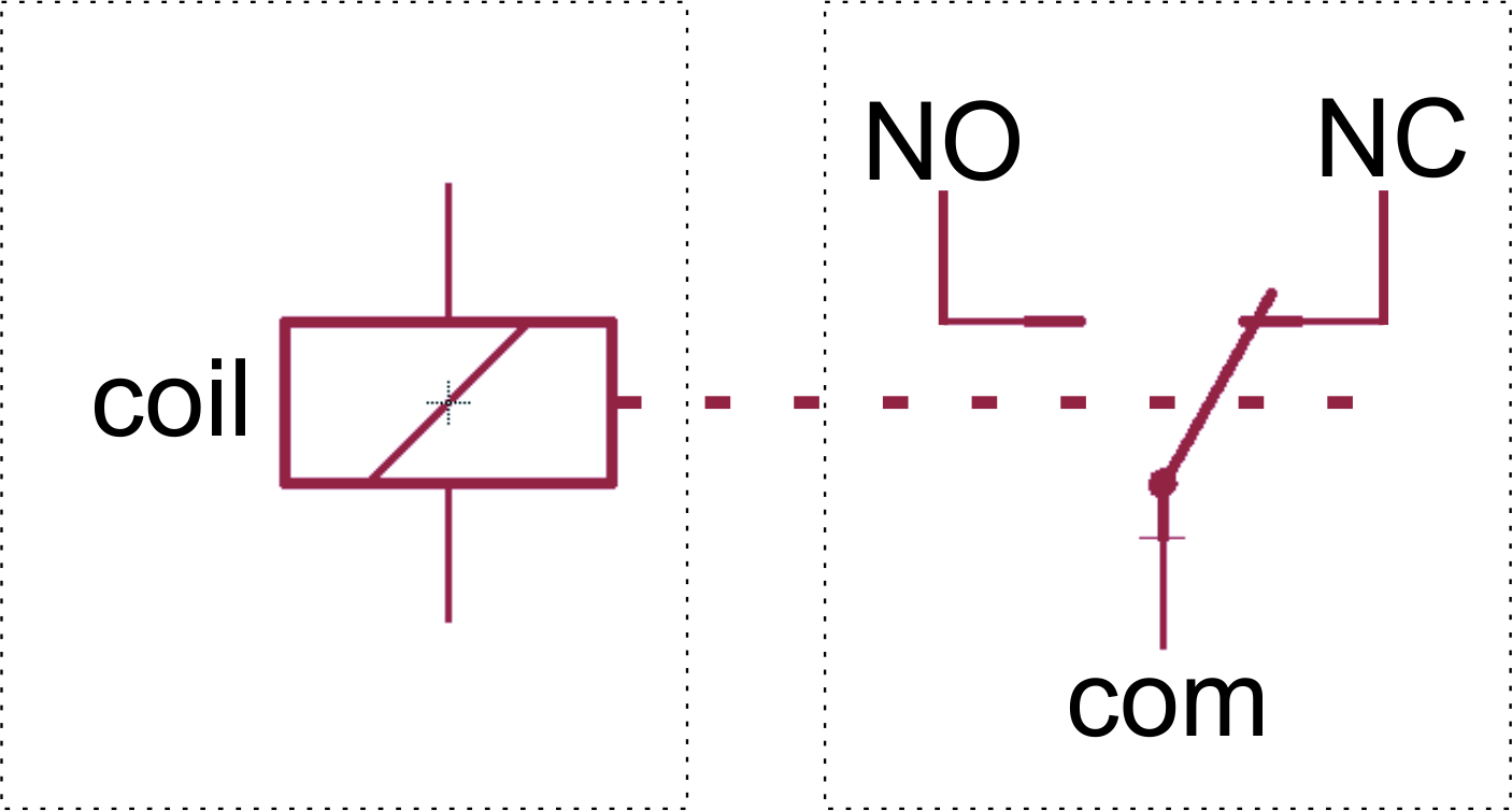
All-or-Nothing Relays Symbols. Name: Operating device, general symbol; Relay coil, general symbol. Form 1. Name: Operating device; Relay coil. Form 1. Remark: With neutral position, self restoring, operating for either direction of current in the winding. Remark: Shown with two stable positions.

relay circuit diagram symbols Wiring Diagram and Schematics
EN 60617: 07-15-01. schematic symbol - Symbol: electrical-installations - relays-and-switches - relay.
Inductor, Relay and Transformer
There are 3 major characteristics that distinguishes the relays: 1. The max voltage: This characteristic is determined by the gap that exists between the contacts, as well as the alloy that the the contact is made of. The higher the gap the higher the voltage that a relay can cut-off.

Relay circuits Relay Circuit Diagram and Operation Relay Schematic
Relay symbols and device numbers; selection from IEC 617-, IEEE C37.2-1991 and IEEE C37.2-1979 1MRK 590 006-BEN Page 2 Symbols and designations (cont'd) SYNC Synchronizing (check) BLOCK Blocking device LO Lock-out TCS Trip circuit supervision X/Y Translation of signal
Relay Symbols Openclipart
A relay Electromechanical relay principle Electromechanical relay schematic showing a control coil, four pairs of normally open and one pair of normally closed contacts An automotive-style miniature relay with the dust cover taken off. A relay is an electrically operated switch.It consists of a set of input terminals for a single or multiple control signals, and a set of operating contact.
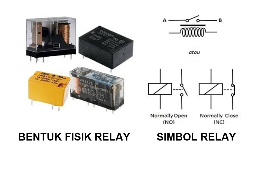
Simbol Relay, Bentuk Fisik Relay, dan Struktur Relay Balagia Blog
Figure 1. Home-made CircuitLab opto-isolators. (a) Standard transistor. (b) Opto-triac using the DIAC symbol as there is no gate terminal. (c) Bidirectional LED (a bit messy). (d) An opto triac or SSR with zero-cross. I recommend showing the innards with enough detail to clearly identify. Function (the LED or switch).
Simbol Elektronik, Relay, Diagram Pengkabelan gambar png
gambar relay. Relay adalah komponen dalam rangkaian elektronika yang berupa saklar atau switch untuk mengontrol sebuah rangkaian listrik dengan mengaktifkan ataupun menonaktifkan kontak saklar. Komponen penyusunnya yakni terdiri dari elektromagnet (coil) dan mekanikal (perangkat saklar). Fungsi dari coil itu sendiri adalah sebagai alat penarik.
Relay, Simbol Elektronik, Diagram Sirkuit gambar png
Relay-Based Logic and the Origins of Ladder Logic Symbols Historical Context. The evolution of ladder logic symbols can be traced back to the historical use of relay-based logic in control systems. Before the advent of programmable logic controllers (PLCs) and standardized programming languages like those defined in IEC 61131-3, industrial.
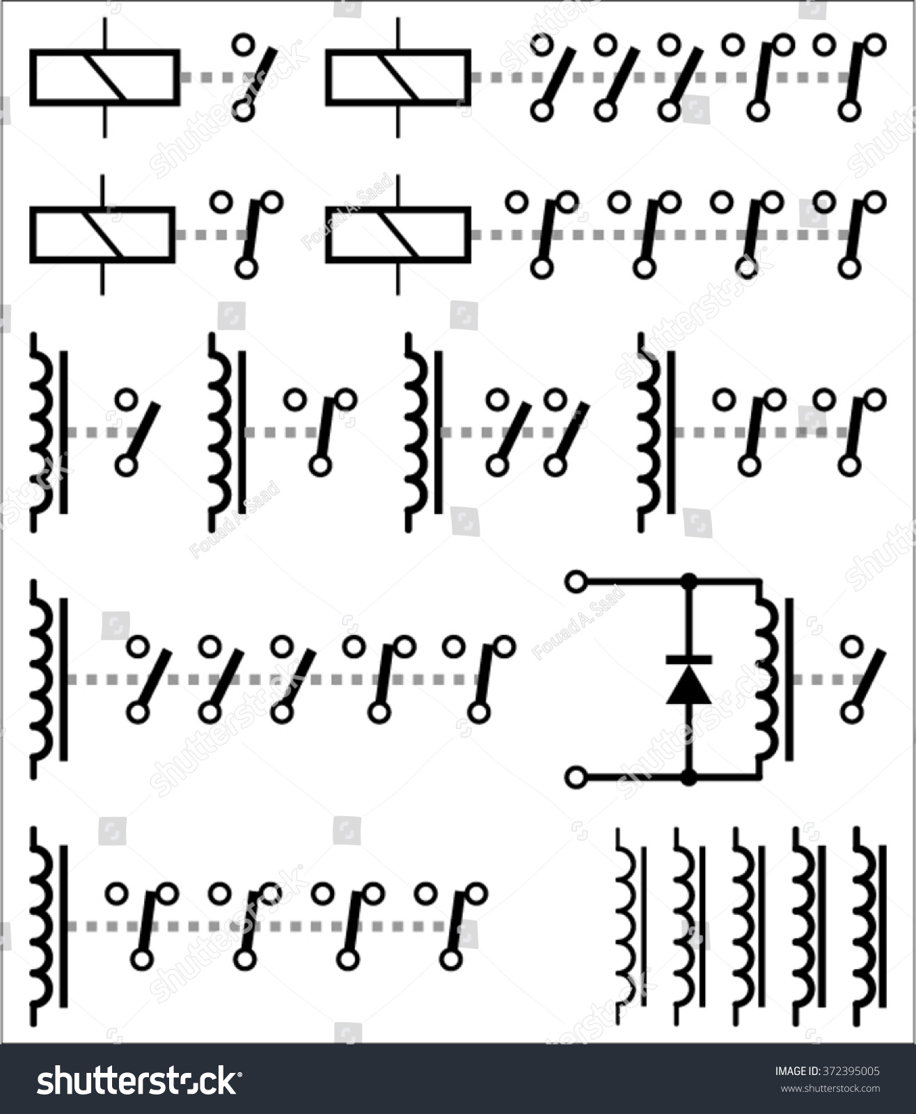
Electromechanical Relay Symbols Stock Vector 372395005 Shutterstock
5. Relay coil. The relay coil symbol is used to indicate control relay or motor starter and sometimes even contactor or timer. 6. Pilot Lamp. The given symbol denotes Pilot Lamp or simply a bulb. They indicate the machine operation. Relay Logic Circuit - Examples and Working. The working of a relay logic circuit can be explained through the.
Fungsi Relay dan MacamMacam Relay otomotif
Pengertian Relay dan Fungsinya. Dickson Kho Komponen Elektronika. Pengertian Relay dan Fungsinya - Relay adalah Saklar ( Switch) yang dioperasikan secara listrik dan merupakan komponen Electromechanical (Elektromekanikal) yang terdiri dari 2 bagian utama yakni Elektromagnet (Coil) dan Mekanikal (seperangkat Kontak Saklar/Switch).
what is relay projectiot123 esp32,raspberry pi,iot projects
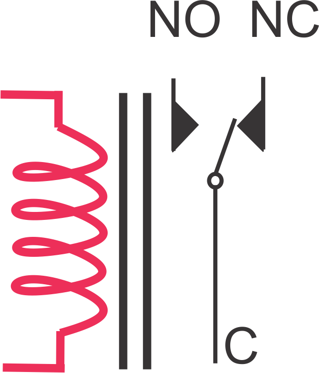
Relay Symbols and Electromagnets. The relay are switching electrical devices activated by signals. Most of the time, a small voltage or current is used to switch other voltages or higher currents that may be electromechanical or fully electronic type. The electromagnetic controls are activated thanks to electromagnetic fields generated by.

Relay Wiring Diagram Symbols
Electrical Relay Diagram Symbols www.industrialtext.com 1-800-752-8398 Connections, Etc. (cont.) Ground Chassis Or Frame Not Necessarily Grounded Plug and Recp. Contacts Time Delay After Coil Normally Open Normally Closed Normally Open Normally Closed Relay, Etc. Normally Open Normally Closed Thermal Over-Load GRD CH RECP PL TR TR TR TR CR M.
mamentronika Modul Relay
The (NC) relay is the opposite of the normally open relay in function. When the relay's high amperage route's links (Terminal 30 and 87) are closed (Touch) each other without energizing the relay in normal conditions, called Normally-Closed (NC). The (NC) relay's links are closed by default and have a connection.